![]()

"
"Radom District Heating"
The district heating is composed of two heat sources: the "North" Heat Plant, the "South" Heat Plant as well as the heating network.

Figure: Heating networks and district heating stations in the city.
The heating network system is 167.8 km in length and provides heat to 941 district heating substations, 631 of which are state-of-the-art fully automated and metered substations being the property of "RADPEC". Upon project implementation, as much as 67% of the heating network in Radom is a pre-insulated network.
"Reduction of energy losses at the Radom district heating"
"RADPEC" SA project co-financed by the EU from the Cohesion Funds within the framework of the Infrastructure and Environment Programme.
.
 In reply to the call as published within the framework of Measure 9.2 Efficient energy distribution, on 5 July 2010 RADPEC submitted an application to the office of the National Fund for Environmental Protection and Water Management together with the required application documents necessary to implement the project entitled "Reduction of energy losses at the Radom district heating". The project was put on a reserve list.
Photo: The documents are being packed
 On 4 December 2012, on the webpages of the National Fund for Environmental Protection and Water Management the Final List of projects was published which received a positive level 2 substantive assessment within the framework of Call No. 1 for Measure 9.2. RADPEC was also included in the group of the projects with a positive assessment.
As a reserve list candidate, upon continued efforts to obtain funds from the National Fund for Environmental Protection and Water Management, "RADPEC" succeeded in winning project co-financing in 2012.
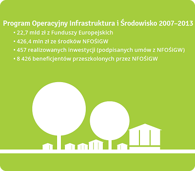
PROGRAMME: Infrastructure and Environment Operational Programme
PRIORITY 9: Environment-friendly energy infrastructure and energy efficiency
MEASURE 9.2: Efficient energy distribution
On 28 December 2012, a project co-financing contract was signed.
Planned total cost of the project: PLN 47,661,777.31
Maximum amount of eligible expenditure: PLN 30,623,105.00
EU contribution: PLN 25,854,944.00
Pursuant to the terms and conditions of the contract concluded with the National Fund for Environmental Protection and Water Management based in Warsaw, "RADPEC" was obliged to re-build the old heating networks (executed in the duct system technology) to create new pre-insulated networks. The majority of the new networks was to be executed as a 'plus' insulation technology, i.e. with an increased insulation thickness.
Apart from network replacement, the activities undertaken were to comprise the modernization of the district heating substations as well.

RADPEC obtained co-financing from the National Fund for Environmental Protection and Water Management in a form of a bridge loan amounting to PLN 25,854,944.00 and a loan amounting to PLN 4,768,161.00.
The loans covered 100% of the eligible costs.
The material scope of the project included 30 tasks related to the reconstruction of the district heating and modernization of the district heating substations:
- replacement of 23.21 km of the district heating pipes with nominal diameters ranging from 32 to 600 mm,
- modernization of 160 of individual district heating substations,
- modernization of 23 of group district heating substations.
10 of the above-stated 30 tasks were implemented using own funds (5.7 km of the pipes).
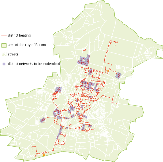
Fig. "Map with marked district networks to be modernized".

With reference to the savings resulting from the tenders carried out, "RADPEC" applied three times at the National Fund for Environmental Protection and Water Management for expansion of the material and financial scope of the project with 17 additional tasks.
• On 10 October 2013 "RADPEC" applied for project expansion with 4 additional tasks.
• 17 February 2015 – application for project expansion with 9 additional tasks.
• 26 May 2015 – application for project expansion with 4 additional tasks.
Total material scope of the project:
• replacement of 30.73 km of the district heating pipes of diameters ranging from 32 to 600 mm with pre-insulated ones,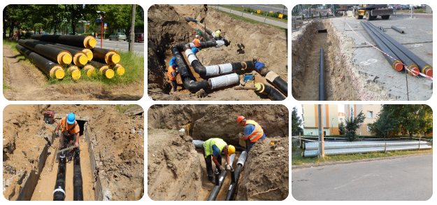
• modernization of 194 of individual district heating substations,
• modernization of 21 of group district heating substations.
RADPEC modernized pipes with diameters ranging from 32 to 80 (14,624.95 m), pipes with diameters ranging from 100 to 250 (11,844.94 m) as well as main pipelines with diameters ranging from 300 to 600 (4,265.2 m).
The results of the projects following project implementation:
• annual consumption of thermal energy lower by 75,888 GJ per year,
• reduction of carbon dioxide emissions by 19,770 tonnes,
• increased safety of heat supplies as a result of decreased breakdown risk.
75,888 GJ of thermal energy is enough to ensure heat supplies to 40 medium-size schools for a year.
Total cost of the project: PLN 57,077,588.67
EU contribution: PLN 33,281,502.72

Photo: Project promotion

On March 5, 2014, RADPEC SA has concluded an agreement with the National Fund for Environmental Protection and Water Management relating to the Project entitled: Limiting of flue gas emission by means of modernising the WR-25 boilers at "RADPEC" SA. The Project consists in developing a system which will increase flue gas dedusting efficiency and increase performance of two WR-25 boilers at the "Północ" Heat Plant. The estimated eligible costs amount to PLN 3,195,000, of which 30% will be co-financed by the Norwegian Financial Mechanism. The investment will result in increasing air protection and adjusting the existing systems to the requirements of the 2001/80/EC directive on limitation of emissions of certain pollutants into the air from large combustion plants (above 50 MW).
Planned ecological effect:
CO2 [Mg/year] - 678
SO2 [Mg/year] - 2.3
NOX [Mg/year] - 0.8
CO [Mg/year] - 0.3
Dust [Mg/year] - 1.8
Parameters before modernisation

The table shows the measured values of pollution concentration in flue gas at the "Północ" Heat Plant
(source: Application for granting an integrated permit for the "Północ" Heat Plant, Energoprojekt, Katowice 2004).
In the figure next to the table we can see a typical set of two six-cyclone batteries and exhaust fans. From 2004 on, the boiler fans were gradually equipped with variable speed control systems, i.e. inverters.

Dedusting of flue gas at the WR25 boiler no. 4. The cyclone system insulated with enclosure made of corrugated steel sheets and mineral wool. This system will be the subject of modernisation in 2015 thanks to the sources obtained from the Norwegian funds.
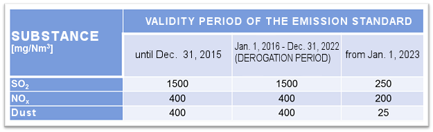
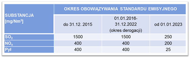
Emission standards for the TC II emitter ("Północ" Heat Plant) after obtaining derogation.
Project assumptions:
• Development of a cyclone filter system as a replacement of the cyclone system of the WR 25 boiler,
• Achieving dedusting efficiency below 100mg/nm3 converted into 6% O2,
• Possibility of various modes of operation of the cyclone filter:
o Operation only by a set of the mechanical cyclone dedusters with boiler operation under reduced load (to approx. 15 MW), guaranteeing dust emission below 100 mg/Nm3 converted into 6% O2.
o Operation using only the bag deduster with boiler operation under reduced load (to approx. 15 MW), guaranteeing dust emission below 100 mg/Nm3 converted into 6% O2.
o Operation at full load of the boiler (from 20MW to 29 MW depending on the fuel calorific value) in a mixed (parallel) bag filter and mechanical system, guaranteeing dust emission below 100 mg/Nm3 converted into 6% O2.

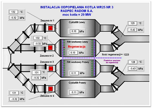
Flue gas dedusting system after modernisation
The figure shows the dedusting system downstream the boiler. After passing through the preliminary dedusting at the Multicyclone Flue Gas Deduster (MFGD), flue gas is directed to the cyclone filter (a parallel bag filter and cyclone system). The MFGD will feature a newly-built cyclone system (1) for preliminary suction, which increases the efficiency of dedusting. Then flue gas is directed as follows depending on the adopted mode of operation: to the bags (3), to the cyclones (4) or to the bags and cyclones in parallel. The exhaust fans direct flue gas to the stack through ducts. The dust is removed through exhaust pipes (11) to the pipe and plate conveyor.
Block diagram of the flue gas system of the modernised WR 25 boiler:

The efficiency values of the MFGD device and the cyclone filter shown on the block diagram are declared by the manufacturer. General efficiency (curly brackets 98.8%) is the efficiency actually measured by an independent laboratory. The efficiency was obtained with fuel with the following properties: 24/16/06 (calorific value MJ/t / ash content under operational conditions / sulphur content). It shall be stressed that in case of mechanical dedusters, the ash content in the coal is important. If this value is several percent higher, dedusting efficiency decreases dramatically.
The operator has an insight into the system parameters by means of the computer visualisation.
Asix system screen shot
Continuous emission measurement:

Screen shot of the momentary continuous emission measurement.
The currently allowable emission values are highlighted in red.
The WR 25 boiler after modernising the pressure part and the boiler setting

In case of reduction of dusts, general tightness of the boiler is very important. Prior to the modernisation of the dedusting system it is important to modernise the pressure part and the boiler setting.

Preliminary MFGD with the suction system.
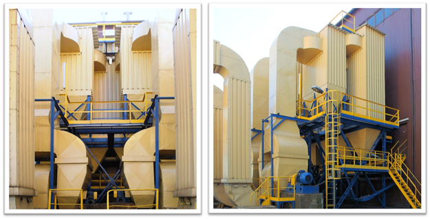
WR 25 boiler - dedusting.

Discharge of dusts from the cyclone filter of the WR 25 boiler no. 3

Supply and regulation of all boiler fans is completed via frequency converters. The photo shows the cabinet with converters.
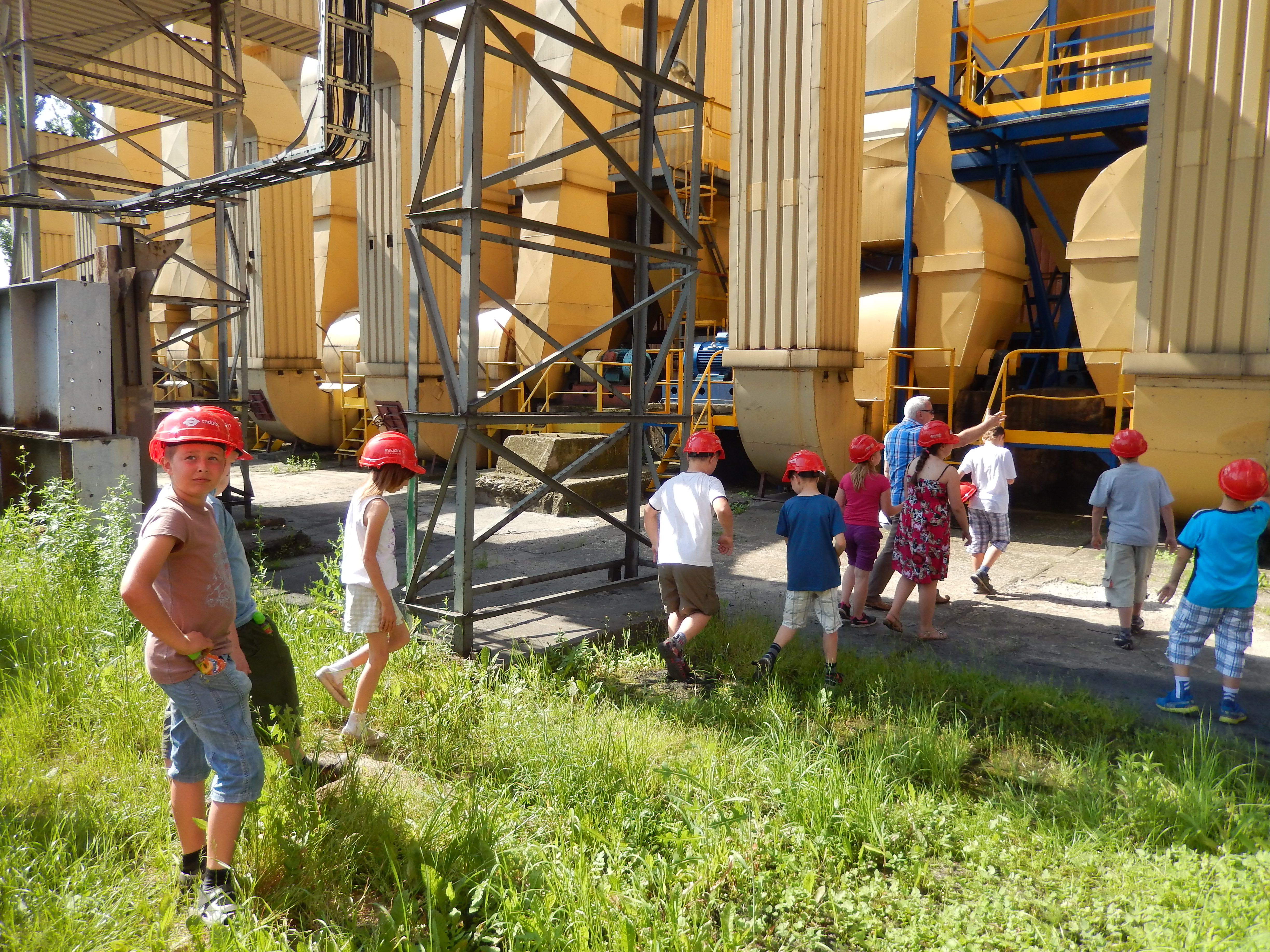
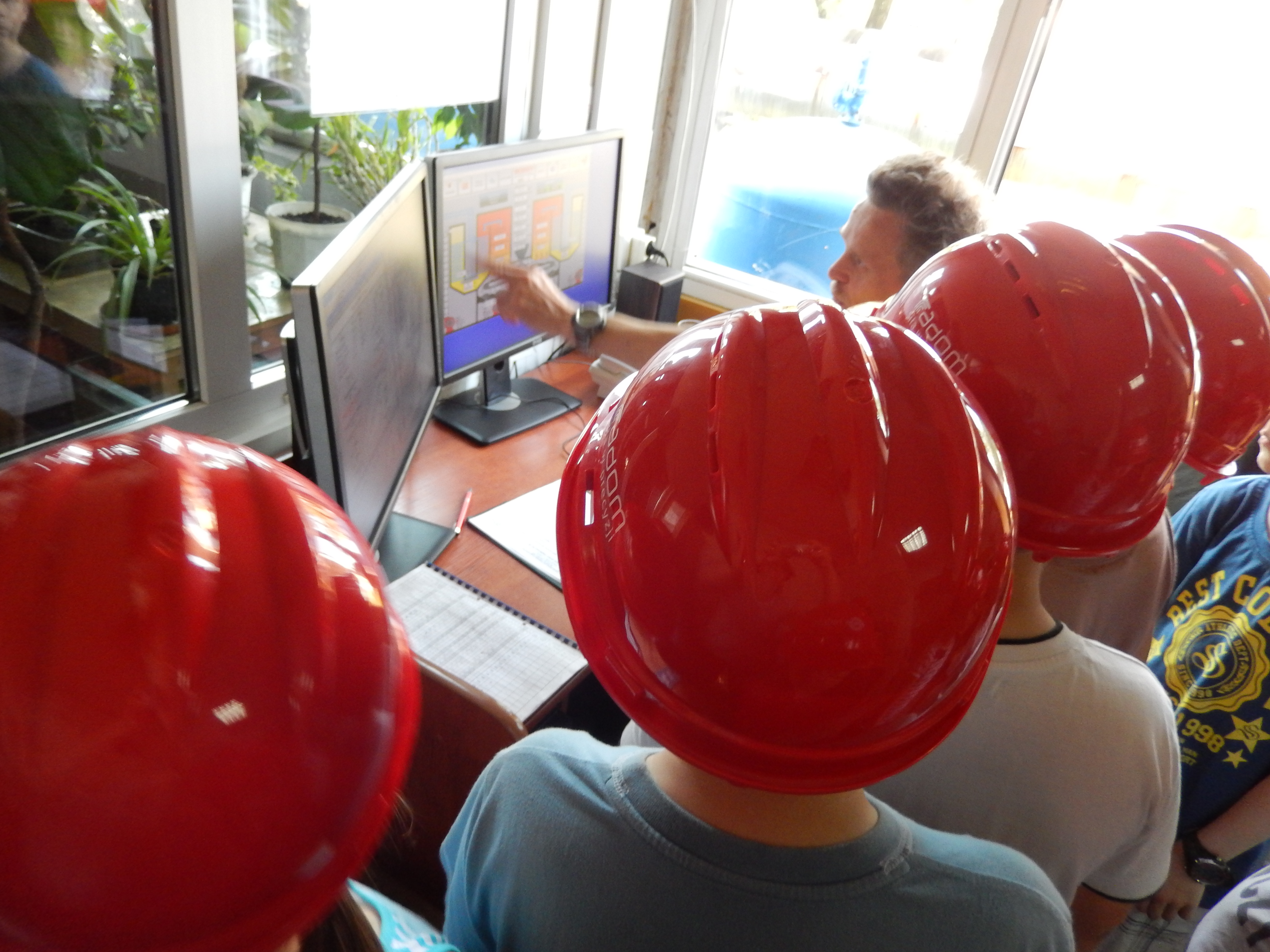
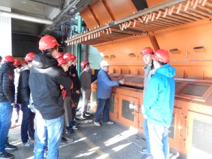
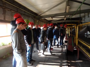
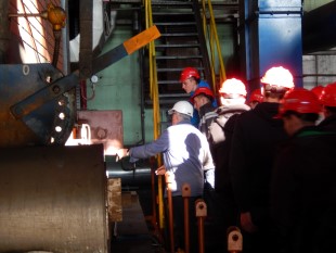
In 2014, Radomskie Przedsiębiorstwo Energetyki Cieplnej „RADPEC" Spółka Akcyjna organised two school educational trips to the "Północ" Heat Plant as a part of promotional activities dedicated to rising awareness about the meaning of Norwegian Financial Mechanism for the implementation of the "Limiting of flue gas emission by means of modernising the WR-25 boilers at RADPEC S.A." Project. Promotional activities are performed in accordance with the "Regulation on the implementation of the Norwegian Financial Mechanism 2009-2014 adopted by the Norwegian Ministry of Foreign Affairs pursuant to Article 8.8 of the Agreement between the Kingdom of Norway and the European Union on a Norwegian Financial Mechanism for the period 2009-2014 on 11 February 2011, as amended on 15 December 2011 and on 14 March 2013", especially with Annex 4 – "Information and Publicity Requirements".
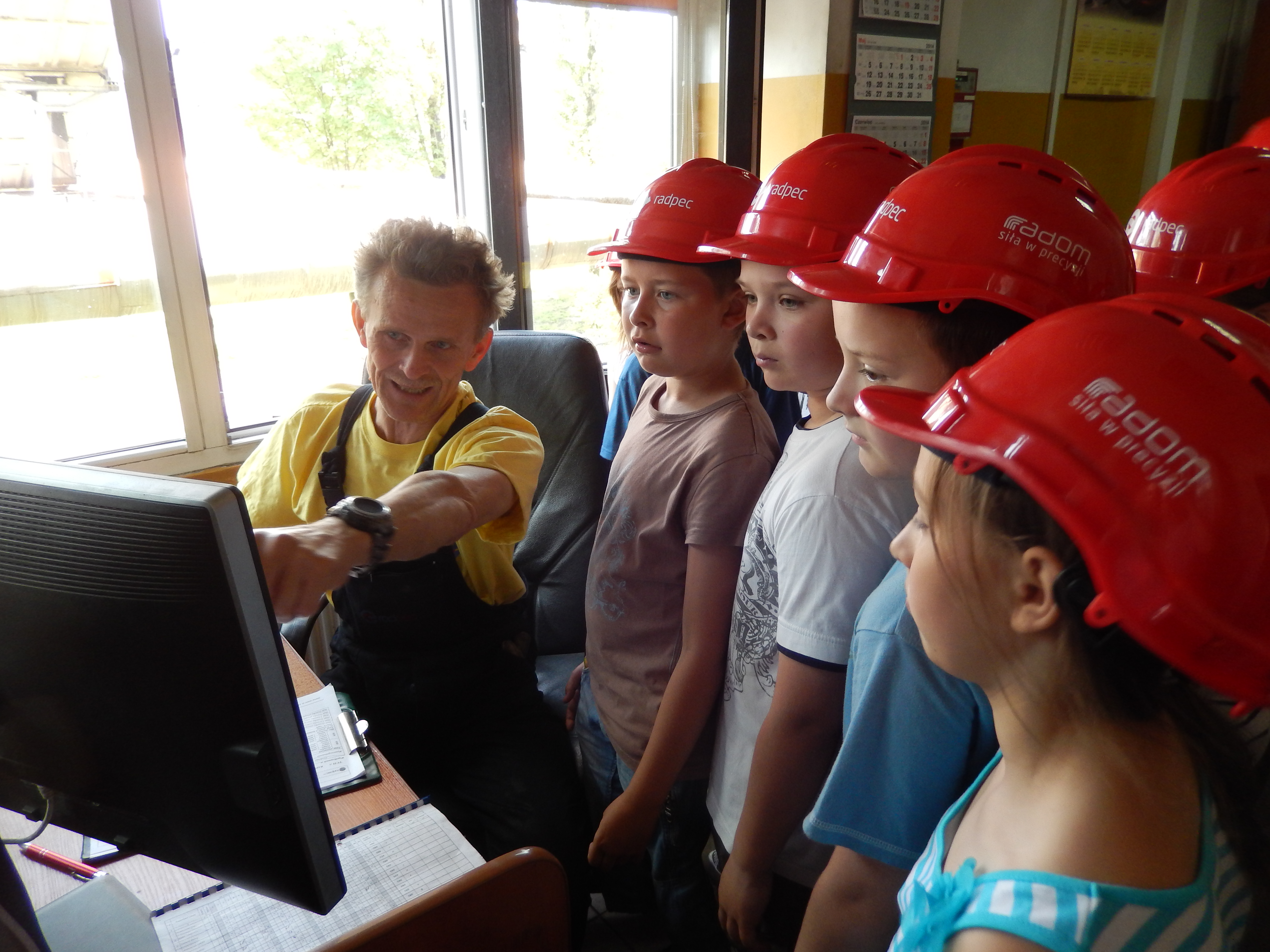
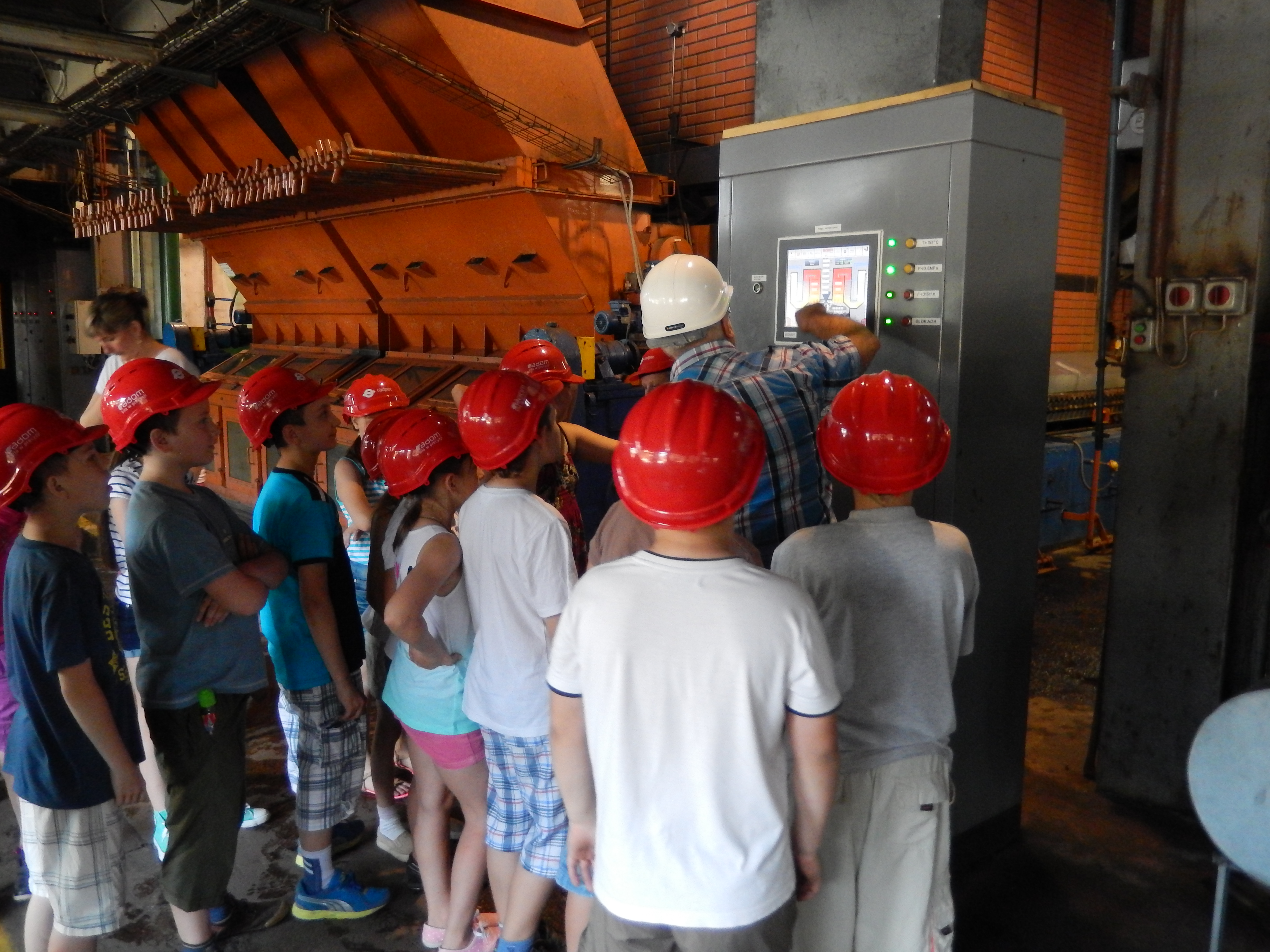
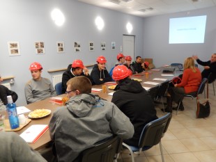
1. The first educational school trip to the "Północ" Heat Plant, where the Project is implemented, took place at 10 June 2014. The participants were students from the nearby tuition-free Primary School (PSP no. 19 in Radom) who first took part in the presentation "Where does the heat come from?".
After the first activity, students took a tour around the “Północ” Heat Plant, discovering what the heat generation looks like and how the “Limiting of flue gas emission by means of modernising the WR-25 boilers at RADPEC S.A.” Project is implemented. During the tour, students learnt what ecological effects the Project will have after its completion. They also found out that the project is being implemented thanks to Norwegian Financial Mechanism grants.


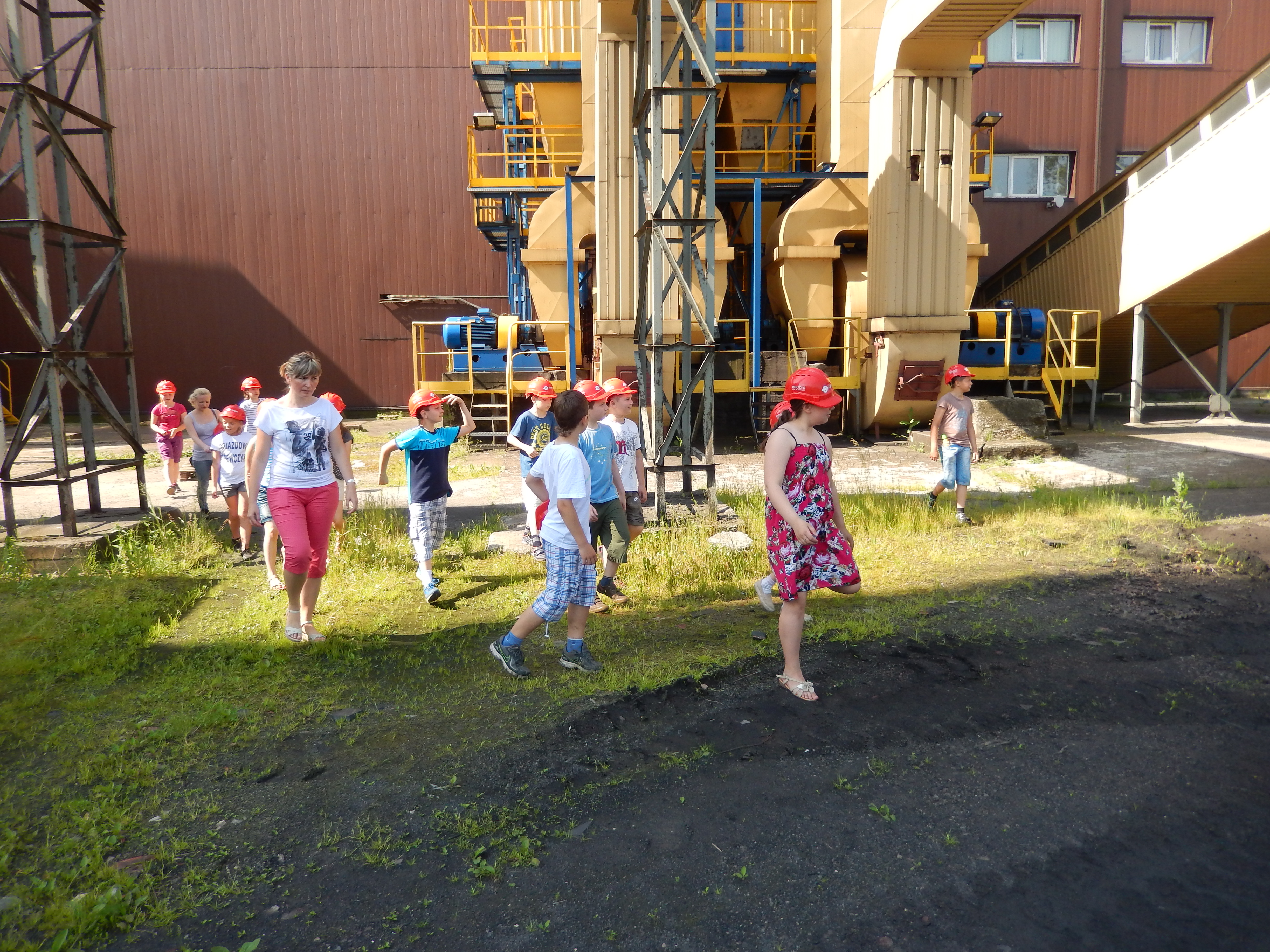

After the tour, students took part in the competition testing their knowledge gained during the visit. The winners were awarded with special RADPEC gadgets (crayon boxes, pendants and reflective lights). All children were given the “Czerwony Kapturek w mieście” [Red Riding Hood in the city] storybook – an educational tale about smart use of heat power and environment protection.
2. The second educational school trip was organised on 29 October 2014 for the students of the Secondary Technical School of Electrical Engineering which is part of the Tadeusz Kościuszko Technical School Complex in Radom. Students, preparing to become power technicians, first took a tour around the plant and then watched a presentation about “Limiting of flue gas emission by means of modernising the WR-25 boilers at RADPEC S.A.” Project, co-financed by Norwegian Financial Mechanism. They were also given informational materials about the project (fliers and print-outs from the presentation).


The last part of the visit was a tour around the “Północ” Heat Plant, where the students had an opportunity to view the development of the Project which they learned about from the presentation.

Implementation of the 2nd stage of the Norway grants project

The scope of the second stage included:
1. Modification of the third pass of the boiler (WR-25 no. 4) including installation of an additional water heater instead of the existing tubular water heater.
2. Execution of heating surface automatic cleaning installation based on the Entex technology.
3. Purchase and installation of pyrite flaps (2 pcs.)
4. Execution and installation of pyrite funnel manholes (2 pcs.).
5. Safety valve replacement (2 pcs.).
6. Execution of new thermal insulation of the boiler.
7. Supervision over boiler drying as performed by the investor representatives (servicing the "North" Heat Plant).
Blow air system modernization executed under the project included:
1. Modernization of the boiler-side air system together with the change of the place of blow air fan installation (moved to the deslagging level), execution of new air suction and feed ducts. The fan intake ports were installed at the stoker level (as in case of other boilers).
2. Execution and installation of two radiator air heaters.
3. Replacement of the existing WWOax-63 blow fans with the new ones applying the parameters appropriate for the WR-25 boiler, in a sound-proof casing with fan inlet and outlet silencers.
4. Development of technical and as-built documentation of the blow air system.
The scope of works related to the Instrumentation, Control and Automation (ICA) under the project comprised:
• replacement of water and flue gas temperature measurement systems at the WR 25 boiler no. 4,
• replacement of pressure measurement systems at the WR 25 no. 4 boiler,
• installation of water heater control valves automatically controlled from the control panel of the ICA control cabinet at the WR 25 no. 4 boiler,
• assembly and start-up of boiler power system, control system and measurement visualization.
The scope of electrical works comprised:
• modernization of the power system of the primary blow air system, moving the power and control routing of the blow fan motors to the deslagging level,
• replacement of the power, measurement and control routing within the WR 25 no. 4 boiler with wire mesh cable trays together with accessories.
Dedusting system modernization consisted in the following:
1. Disassembly of the existing system of flue gas cyclone separators as well as flue gas ducts in the scope enabling cyclo-filter installation.
2. Execution and assembly of a cyclo-filter system in place of cyclone batteries with a possibility of alternative operation (bag, mechanical and mixed operation in a parallel system).
3. Execution of the dedusting system retaining the existing mode of flue gas removal via fans with 75kW motors (2 pcs.).
4. Replacement of flue gas ducts from the boiler to the flue gas fans together with installation of slide gate valves enabling operation in 2 dedusting options as above.
5. Adaptation of ash chutes to the existing FULMAR 125 transport system collecting dust which accumulates below the installed cyclo-filter.
6. Execution of a comprehensive set of cyclone separator operating platforms made of WEMA grating with safety railing and ladders covered with yellow warning corrosion-resistant coating.
7. Execution of thermal insulation of the new flue gas dedusting system, made of mineral wool, coated steel and coated corrugated steel cladding.
8. Performance of high-temperature corrosion-resistant coating of the executed and installed elements.
9. Development of technical documentation within the scope of construction, assembly and start-up works.
10. Replacement of flue gas ducts executed for the purposes of cyclo-filter.
11. Execution of the compressed air installation providing cyclo-filter cleaning agent.
12. Replacement of WPWD - 80/1.8 flue gas fan rotors, flue gas fan housing, flue gas bearing housing and bearings, omega couplings, fan balancing.
13. Measurements confirming the dedusting efficiency as assumed above for each option.
Modernization of the dedusting system was assisted with a relevant scope of electrical and ICA works.

Photo 1: Installation of the draft passage fan housing
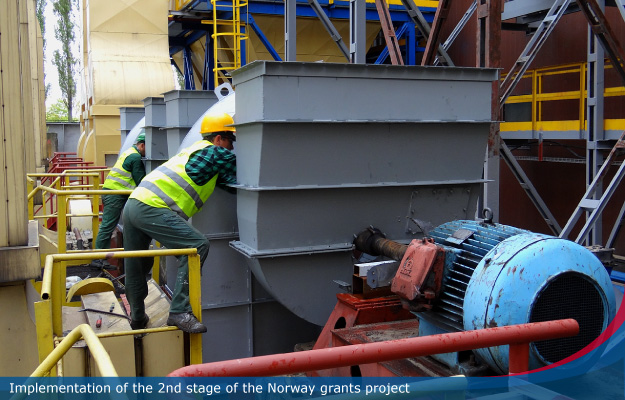
Photo 2: Installation of the draft passage fan compartment

Photo 3: as above

Photo 4: Painting of the dust collector supporting structure

Photo 5: Installation of the flue gas duct components of the draft passage fan

Photo 6: Installation of the flue gas duct thermal insulation and protective plates

Photo 7: Final visual effect
On 31 December 2015, RADPEC S.A. held a press conference connected with the completion of the “Reduction of Flue Gas Emission by Modernizing the WR-25 Boilers” project. The project was conducted from June 2012 until December 2015 within the framework of the Norwegian financial mechanism.
The attendees of the press conference were provided with key information about the completed project: a system due to which the boiler’s efficiency and flue gas dedusting effectiveness were increased. The presentation was followed by a reference visit at the investment project site.

The conference was attended by Zbigniew Słowiński – Deputy Chief Technology Officer, who discussed the project and presented its stages, Barbara Kaleta – acting as Financial Director, who presented financial aspects of the project, as well as top management of the Company.
On July 28, 2016 Radomskie Przedsiębiorstwo Energetyki Cieplnej RADPEC S.A. received information from National Fund of Environment Protection and Water Management, that the Final Report realization of project entitled: Limiting of flue gas emission by means of modernising the WR-25 boilers at "RADPEC" SA. was approved.
According to this, RADPEC S.A. on August 10, 2016 received final payment in amount of 540 000 PLN, and this is treated as formal project completion.

Radomskie Przedsiębiorstwo Energetyki Cieplnej "RADPEC" Spółka Akcyjna is a company with 49 years of tradition. Its field of activity is generation and distribution of heat.
The Municipality of Radom is a majority shareholder of the company.
"RADPEC" own the town's heating network. Its length is 167.8 km and it supplies heat to 941 district heating substations, 631 of which are modern, fully automated stations fitted with metering equipment and operated by the company.
The company generates system heat which is distributed to residential buildings, industrial plants, institutions and public utility facilities.
In 2004 Polish Center for Research and Certification granted RADPEC with the Integrated Management System Certificate: "Quality, Health, Safety & Environment". This certificate confirms that the company complies with the international ISO 9001, ISO 14001 Standards and Polish PN-ISO 45001 standard. In 2013, the renewal audit was carried out successfully, and the company was awarded with the ISO certificate for the next three years.
Main goal of RADPEC is to fully satisfy its clients and to win recognition as a reliable company which is taking into account best interest of all its partners, shareholders and employees.
Radomskie Przedsiębiorstwo Energetyki Cieplnej "RADPEC" Spółka Akcyjna
Address: ul. Żelazna 7, 26-616 Radom
Phone/fax: +48 48 36 255 00
www.radpec.com.pl
KRS no. 0000050068
NIP no.: 796-01-01-620
Share capital: 119,719,570.00 PLN (paid in full)
REGON no.: 670929493
Bank account (at PEKAO S.A.): 04 1240 5703 1111 0000 4897 3254

RADPEC SA podpisał 5.03.2014 r. umowę z Narodowym Funduszem Ochrony Środowiska i Gospodarki Wodnej w sprawie Projektu „Ograniczenie emisji spalin poprzez modernizację kotłów WR-25 w RADPEC S.A.". Projekt polega na zbudowaniu instalacji zwiększającej skuteczność odpylania spalin oraz podwyższającej sprawność dwóch kotłów WR-25 w Ciepłowni „Północ". Szacowane koszty kwalifikowane wynoszą 3195000 zł, z czego 30% będzie dofinansowane z Norweskiego Mechanizmu Finansowego. Inwestycja spowoduje wzrost ochrony powietrza i dostosowanie istniejących instalacji do wymagań wynikających z Dyrektywy 2001/80/WE w sprawie ograniczenia emisji niektórych zanieczyszczeń do powietrza ze źródeł spalania o mocy powyżej 50 MW.
Planowany efekt ekologiczny
CO2 [Mg/rok] - 678
SO2 [Mg/rok] - 2,3
NOX [Mg/rok] - 0,8
CO [Mg/rok] - 0,3
pył [Mg/rok] - 1,8
Parametry przed modernizacją
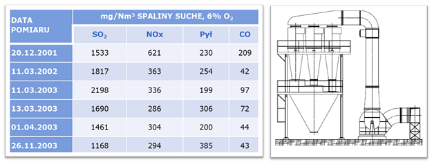
Tabela przedstawia mierzone wartości stężeń zanieczyszczeń w spalinach w Ciepłowni „Północ"
(materiał źródłowy: Wniosek o wydanie pozwolenia zintegrowanego dla Ciepłowni „Północ" Energoprojekt Katowice 2004 r.)
Na rysunku obok tabeli widzimy typowy układ dwu baterii sześcio-cyklonowych i wentylatorów wyciągowych. Od roku 2004 sukcesywnie wyposażano wentylatory kotłów w układy regulacji zmienoobrotowej - falowniki.
Odpylanie spalin na kotle WR25 nr 4. Układ cyklonowy w zabudowie izolacji z blachy falistej i wełny mineralnej. Układ ten będzie przedmiotem modernizacji w roku 2015 dzięki środkom pozyskanym z funduszy norweskich.
Standardy emisyjne dla emitora TC II (Ciepłowni "Północ") po uzyskaniu derogacji.
Założenia projektowe:
Układ odpylania spalin po modernizacji
Rysunek przedstawia instalację odpylania za kotłem. Po przejściu przez wstępne odpylanie w Multicyklonowym Odpylaczu Spalin (MOS) spaliny kierowane są na cyklofiltr (układ równoległy filtra workowego i cyklonów). Na MOS-ie dobudowany został cyklonowy układ odsysania wstępnego (1) zwiększający sprawność odpylania. Następnie spaliny kierowane są w zależności od przyjętego wariantu pracy: na worki (3), na cyklony (4) lub równolegle na worki i cyklony. Wentylatory wyciągowe, za pomocą kanałów kierują spaliny do komina. Pył odprowadzany jest za pomocą rur spustowych (11) do przenośnika rurowo-talerzykowego.
Schemat blokowy układu spalin zmodernizowanego kotła WR 25:

Sprawności urządzenia MOS i cyklofiltra, pokazane na schemacie blokowym, są sprawnościami deklarowanymi przez producenta. Sprawność ogólna (nawias klamrowy 98,8%) jest sprawnością zmierzoną fizycznie przez niezależne laboratorium. Sprawność została uzyskana przy paliwie 24/16/06 (kaloryczność MJ/t / popiół roboczy / zawartość siarki). Należy podkreślić, że w przypadku odpylaczy mechanicznych istotną rolę odgrywa zawartość popiołu w węglu. Kilkuprocentowy wzrost tej wartości powoduje lawinowe zmniejszenie skuteczności odpylania.
Palacz ma podgląd parametrów instalacji poprzez wizualizację komputerową.
Zrzut ekranowy z systemu asix
Pomiar ciągły emisji:
Zrzut ekranowy chwilowego ciągłego pomiaru emisji.
Na czerwono zaznaczono aktualnie dopuszczane normy emisji.
Kocioł WR 25 po modernizacji części ciśnieniowej i obmurza
W przypadku redukcji pyłów bardzo ważną rolę odgrywa ogólna szczelność kotła. Przed modernizacją instalacji odpylania ważne jest wykonanie modernizacji części ciśnieniowej wraz z obmurzem kotłów.
Odpylacz wstępny MOS z odsysaniem.
Kocioł WR 25 - odpylanie.
Odprowadzenie pyłów z cyklofiltra kotła WR 25 nr 3
Zasilanie i regulacja wszystkich wentylatorów kotła odbywa się poprzez przemienniki częstotliwości. Na zdjęciu szafa z przemiennikami.
Radomskie Przedsiębiorstwo Energetyki Cieplnej „RADPEC" Spółka Akcyjna zorganizowało w roku 2014 dwie wycieczki szkolne do Ciepłowni „Północ". Stanowiły one element działań promocyjnych służących podnoszeniu świadomości publicznej o znaczeniu Norweskiego Mechanizmu Finansowego dla wdrażania projektu „Ograniczenie emisji spalin poprzez modernizację kotłów WR-25 w RADPEC S.A.". Działania promocyjne są realizowane zgodnie z „Regulacjami w sprawie wdrażania Norweskiego Mechanizmu Finansowego na lata 2009-2014 przyjętymi przez norweskie Ministerstwo Spraw Zagranicznych zgodnie z art. 8.8 Umowy pomiędzy Królestwem Norwegii a Unią Europejską w sprawie Norweskiego Mechanizmu Finansowego na lata 2009-2014 w dniu 11 lutego 2011 r., zmienione w dniu 15 grudnia 2011 r. oraz 14 marca 2013 r.", a w szczególności z Załącznikiem nr 4 - „Wymogi dotyczące Informacji i Promocji".
1. W pierwszej wycieczce do Ciepłowni „Północ"(10.06.2014), gdzie realizowany jest Projekt, wzięli udział uczniowie pobliskiej publicznej szkoły podstawowej (PSP nr 19 w Radomiu). Najpierw została im przedstawiona prezentacja pt. „Jak powstaje ciepło?".
Po zapoznaniu się z prezentacją młodzież szkolna zwiedziła Ciepłownię „Północ", gdzie zobaczyła jak w praktyce wygląda produkcja ciepła oraz jak przebiega wdrażanie projektu „Ograniczenie emisji spalin poprzez modernizację kotłów WR-25 w RADPEC S.A.". W trakcie zwiedzania ciepłowni uczniowie dowiedzieli się o efektach ekologicznych, jakie przyniesie zrealizowany Projekt. Zostali też poinformowani, iż Projekt powstaje dzięki dotacji z Norweskiego Mechanizmu Finansowego.
Po wycieczce odbył się konkurs z wiedzy zdobytej podczas zwiedzania ciepłowni. Zwycięzcy konkursu otrzymali nagrody w postaci gadżetów RADPEC-u (paczki kredek do rysowania, breloczki oraz światełka odblaskowe). Wszystkie dzieci otrzymały książeczki „Czerwony Kapturek w mieście" – jest to bajka edukacyjna ucząca mądrego korzystania z ciepła i dbania o środowisko naturalne.
2. Druga wycieczka została zorganizowana w dniu 29.10.2014 r. dla uczniów Technikum Energetycznego wchodzącego w skład Zespołu Szkół Technicznych im. Tadeusza Kościuszki w Radomiu. Uczniom, którzy kształcą się na kierunku „technik energetyk", zaprezentowano najpierw przedsiębiorstwo. Następnie młodzież z Zespołu Szkół Technicznych obejrzała przygotowaną dla niej prezentację na temat współfinansowanego przez Norweski Mechanizm Finansowy projektu pt. „Ograniczenie emisji spalin poprzez modernizację kotłów WR-25 w RADPEC S.A." Młodzież otrzymała też materiały informacyjne o projekcie (ulotki i wydruki z prezentacji).
Ostatnim punktem programu wycieczki było zwiedzanie Ciepłowni „Północ" i zapoznanie się z postępami w realizacji Projektu, o którym dowiedzieli się wcześniej podczas obejrzanej prezentacji.
Drugi etap projektu norweskiego
Realizacja drugiego etapu swym zakresem objęła:
1. Przeróbkę trzeciego ciągu kotła (WR-25 nr 4) z zabudową w miejsce istniejącego rurowego podgrzewacza powietrza dodatkowego podgrzewacza wody.
2. Wykonanie instalacji automatycznego czyszczenia powierzchni ogrzewalnej, w oparciu o technologię firmy Entex.
3. Zakup i montaż klapek pirytowych (2 szt.)
4. Wykonanie i montaż włazów do lejów pirytowych (2 szt.).
5. Wymianę zaworów bezpieczeństwa (2 szt.):
6. Wykonanie nowej izolacji kotła.
7. Nadzór nad suszeniem kotła wykonywanym przez przedstawicieli inwestora (obsługa Ciepłowni „Północ").
Modernizacja powietrza podmuchowego, wykonanego w ramach projektu, obejmowała:
1. Modernizację powietrza przykotłowego wraz ze zmianą miejsca zainstalowania wentylatorów powietrza podmuchowego (przeniesienie na poziom odżużlania), wykonanie nowych kanałów ssawnych i dolotowych. Czerpnie wentylatorów zabudowane zostały na poziomie palacza (jak na pozostałych kotłach).
2. Wykonanie oraz montaż dwóch kaloryferowych podgrzewaczy powietrza.
3. Wymianę istniejących wentylatorów podmuchu typ WWOax-63 na nowe, z zastosowaniem parametrów odpowiednich dla kotła WR-25, w obudowie dźwiękoszczelnej z tłumikami hałasu na wlocie i wylocie wentylatora.
4. Wykonanie dokumentacji technicznej i pomontażowej powietrza podmuchowego.
Zakres AKPiA prac wykonanych w ramach projektu obejmował:
• wymianę układów pomiaru temperatury wody i spalin kotła WR 25 nr 4
• wymianę układów pomiaru ciśnienia kotła WR 25 nr 4,
• montaż zaworów regulacyjnych podgrzewaczy wody, sterowanych automatycznie z panelu operatorskiego szafy sterowniczej AKPiA kotła WR 25 nr 4,
• kompletację, uruchomienie zasilania, sterowania, wizualizacji pomiarów kotła.
Zakres wykonanych prac elektrycznych obejmował:
• modernizację zasilania układu powietrza podmuchowego pierwotnego, przeniesienie tras zasilających i sterowniczych silników wentylatorów podmuchu na poziom odżużlania.
• wymianę tras kablowych zasilających, pomiarowych i sterowniczych w obrębie kotła WR 25 nr 4 na koryta siatkowe wraz z osprzętem.
Modernizacja odpylania polegała na:
1. Demontażu istniejącego układu cyklonowych odpylaczy spalin oraz kanałów spalin w zakresie umożliwiającym montaż cyklofiltra.
2. Wykonanie i montaż układu cyklofiltrów w miejsce baterii cyklonowych z możliwością pracy wariantowej (workowej, mechanicznej oraz mieszanej w układzie równoległym.
3. Wykonanie układu odpylania z zachowaniem istniejącego sposobu odprowadzania spalin wentylatorami, których moce silników wynoszą 75kW (2 szt.)
4. Wymiana kanałów odprowadzania spalin od kotła do wentylatorów spalin wraz z montażem zaworów szybrowych pozwalających na pracę w 2 powyższych wariantach odpylania.
5. Dostosowanie zsypów popiołu do istniejącego przenośnika FULMAR 125 odbierającego pył spod zamontowanego cyklofilra.
6. Wykonanie kompletnych podestów obsługowych odpylaczy cyklonowych z kratek „wema" z barierkami ochronnymi oraz drabinkami zabezpieczonych pokryciem antykorozyjnym oraz ostrzegawczym w kolorze żółtym.
7. Wykonanie izolacji termicznej nowej instalacji układu odpylania z wełny mineralnej oraz poszycia z blachy powlekanej oraz blachy falistej powlekanej.
8. Wykonanie pokrycia antykorozyjnego wysokotemperaturowego wykonanych i za-montowanych elementów.
9. Wykonanie dokumentacji technicznej w zakresie robót budowlanych, montażowych i rozruchowych
10. Wymianę kanałów spalin wykonanych pod potrzeby cyklofiltra.
11. Wykonanie instalacji sprężonego powietrza zapewniającej czynnik czyszczący cyklofiltr.
12. Wymianę wirników wentylatorów spalin typ WPWD - 80/1,8, obudów wentylatorów spalin, obudów łożysk i łożysk wentylatorów spalin, sprzęgieł typu omega, wyważenie wentylatorów.
13. Wykonanie pomiarów potwierdzających założoną powyżej skuteczność odpylania w każdym z wariantów.
Modernizacja układu odpylania wsparta została odpowiednim zakresem elektrycznym i akapowskim.
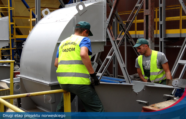
Fot. 1: Montaż obudowy wentylatora ciągu.
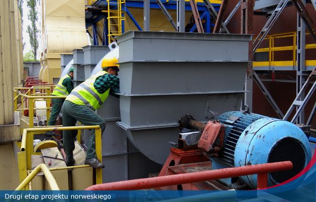
Fot. 2: Montaż kieszeni wentylatora ciągu
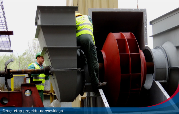
Fot. 3: jw.
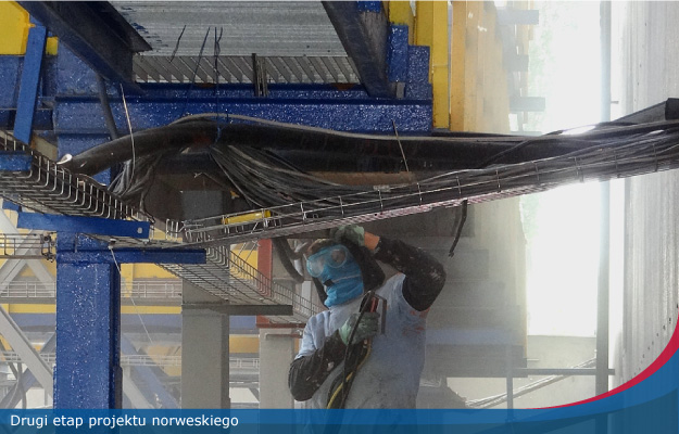
Fot. 4: Malowanie konstrukcji wsporczej odpylaczy

Fot. 5: Montaż elementów kanału spalin wentylatora ciągu
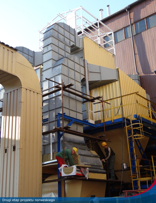
Fot. 6: Montaż izolacji termicznej i blach osłonowych kanałów spalin

Fot.7: Końcowy efekt wizualny
W „RADPEC" S.A. 31 grudnia 2015 roku odbyła się konferencja prasowa związana z zakończeniem projektu „Ograniczenie emisji spalin poprzez modernizację kotłów WR-25". Projekt realizowany był w okresie od czerwca 2012 do grudnia 2015 roku w ramach norweskiego mechanizmu finansowego.
Uczestnikom konferencji przedstawiono najważniejsze informacje o zrealizowanym projekcie, instalacji, dzięki której została podwyższona sprawność kotła i zwiększona skuteczność odpylania spalin. Podsumowaniem prezentacji była wizyta studyjna w miejscu realizacji inwestycji.
W spotkaniu uczestniczyli Zbigniew Słowiński – Wiceprezes ds. Technicznych, który omówił projekt i zaprezentował kolejne etapy jego realizacji, Barbara Kaleta – p.o. Dyrektora ds. Ekonomiczno-Finansowych, która przedstawiła kwestie finansowe realizowanego projektu oraz kadra kierownicza Spółki.

Dnia 28 lipca 2016 roku Radomskie Przedsiębiorstwo Energetyki Cieplnej RADPEC S.A. otrzymało od Narodowego Funduszu Ochrony Środowiska i Gospodarki Wodnej informację,iż zaakceptowany został Raport Końcowy z realizacji projektu pn. „Ograniczenie emisji spalin poprzez modernizację kotłów WR-25 w RADPEC S.A.".
W związku z tym RADPEC S.A w dniu 10 sierpnia 2016 roku otrzymał płatność końcową w wysokości 540 000 PLN i jest to formalne zakończenie projektu.
Informacje zbierane w celu monitorowania i dostosowywania (cookies)
„Cookies" („ciasteczka") to małe pliki tekstowe, przesyłane przez stronę internetową na państwa komputer po to, by umożliwić mu zapamiętanie poszczególnych informacji o sesji połączenia internetowego. Państwa komputer będzie udostępniał informacje zawarte w „cookies" wyłącznie stronie internetowej, z której one pochodzą; nie może o nie występować żadna inna strona internetowa. Są dwa rodzaje „cookies":
Związane z sesją – są one utrzymywane tylko w czasie, w jakim jest uruchomiona przeglądarka. W momencie zamknięcia przeglądarki „cookies" są kasowane. Strony internetowe mogą wykorzystywać „cookies" związane z sesją ze względów technicznych, np. aby umożliwić lepszą nawigację na stronie albo aby umożliwić państwu dostosowanie swoich preferencji związanych z korzystaniem ze strony.
Trwałe – tego rodzaju „cookies" są zachowywane na twardym dysku użytkownika w celu określenia, którzy użytkownicy są nowi na stronie, a którzy wracają; dla powracających użytkowników są one potrzebne do zablokowania powtarzających się zaproszeń do wzięcia udziału w badaniu satysfakcji ForeSee.
Jeśli nie życzą sobie państwo, żeby na państwa komputerze przechowywane były „cookies" - trwałe czy też związane z sesją - możecie państwo wyłączyć cookies w swojej przeglądarce. Nadal będziecie państwo mieli dostęp do wszelkich informacji i zasobów na naszej stronie. Jednak wyłączenie „Cookiem" może mieć wpływ na funkcjonowanie niektórych stron internetowych. Proszę mieć świadomość, że wyłączenie „cookies" w przeglądarce będzie miało wpływ na funkcjonowanie „cookies" na wszystkich innych odwiedzanych przez państwa stronach.
Jak włączyć obsługę plików cookie w swojej przeglądarce?
Podajemy instrukcję jak włączyć obsługę plików cookies w następujących przeglądarkach:
Internet Explorer 7 dla systemu Windows
Firefox 3 dla systemu Windows
Google Chrome dla systemu Windows
Internet Explorer 6 dla systemu Windows
Opera 9 dla systemu Windows
Safari dla systemu Apple OS X
Firefox 3 dla systemu Apple OS X
Strona 2 z 2
NIP: 796-01-01-620
REGON: 670929493
KRS: 0000050068
Spółka wpisana do rejestru sądowego przedsiębiorców prowadzonego przez Sąd Rejonowy Lublin-Wschód w Lublinie z siedzibą w Świdniku, VI Wydział Gospodarczy Krajowego Rejestru Sądowego
Kapitał zakładowy: 119 305 130,00 zł
Radomskie Przedsiębiorstwo Energetyki Cieplnej „RADPEC” Spółka Akcyjna
26-616 Radom, ul. Żelazna 7
e-mail: radpec@radpec.com.pl
e-Doręczenia: AE:PL-98816-78756-FRJFR-29
Centrala: tel. 48 384-69-41 do 45
Sekretariat: tel. 48 384-69-40,
faks 48 362-55-00
Pogotowie cieplne: tel. 993,
48 384-69-32