


On March 5, 2014, RADPEC SA has concluded an agreement with the National Fund for Environmental Protection and Water Management relating to the Project entitled: Limiting of flue gas emission by means of modernising the WR-25 boilers at "RADPEC" SA. The Project consists in developing a system which will increase flue gas dedusting efficiency and increase performance of two WR-25 boilers at the "Północ" Heat Plant. The estimated eligible costs amount to PLN 3,195,000, of which 30% will be co-financed by the Norwegian Financial Mechanism. The investment will result in increasing air protection and adjusting the existing systems to the requirements of the 2001/80/EC directive on limitation of emissions of certain pollutants into the air from large combustion plants (above 50 MW).
Planned ecological effect:
CO2 [Mg/year] - 678
SO2 [Mg/year] - 2.3
NOX [Mg/year] - 0.8
CO [Mg/year] - 0.3
Dust [Mg/year] - 1.8
Parameters before modernisation

The table shows the measured values of pollution concentration in flue gas at the "Północ" Heat Plant
(source: Application for granting an integrated permit for the "Północ" Heat Plant, Energoprojekt, Katowice 2004).
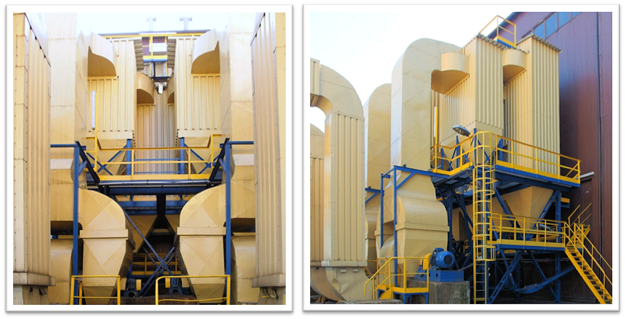
In the figure next to the table we can see a typical set of two six-cyclone batteries and exhaust fans. From 2004 on, the boiler fans were gradually equipped with variable speed control systems, i.e. inverters.

Dedusting of flue gas at the WR25 boiler no. 4. The cyclone system insulated with enclosure made of corrugated steel sheets and mineral wool. This system will be the subject of modernisation in 2015 thanks to the sources obtained from the Norwegian funds.
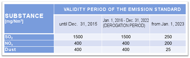
Emission standards for the TC II emitter ("Północ" Heat Plant) after obtaining derogation.
Project assumptions:
• Development of a cyclone filter system as a replacement of the cyclone system of the WR 25 boiler,
• Achieving dedusting efficiency below 100mg/nm3 converted into 6% O2,
• Possibility of various modes of operation of the cyclone filter:
o Operation only by a set of the mechanical cyclone dedusters with boiler operation under reduced load (to approx. 15 MW), guaranteeing dust emission below 100 mg/Nm3 converted into 6% O2.
o Operation using only the bag deduster with boiler operation under reduced load (to approx. 15 MW), guaranteeing dust emission below 100 mg/Nm3 converted into 6% O2.
o Operation at full load of the boiler (from 20MW to 29 MW depending on the fuel calorific value) in a mixed (parallel) bag filter and mechanical system, guaranteeing dust emission below 100 mg/Nm3 converted into 6% O2.

Flue gas dedusting system after modernisation
The figure shows the dedusting system downstream the boiler. After passing through the preliminary dedusting at the Multicyclone Flue Gas Deduster (MFGD), flue gas is directed to the cyclone filter (a parallel bag filter and cyclone system). The MFGD will feature a newly-built cyclone system (1) for preliminary suction, which increases the efficiency of dedusting. Then flue gas is directed as follows depending on the adopted mode of operation: to the bags (3), to the cyclones (4) or to the bags and cyclones in parallel. The exhaust fans direct flue gas to the stack through ducts. The dust is removed through exhaust pipes (11) to the pipe and plate conveyor.
Block diagram of the flue gas system of the modernised WR 25 boiler:

The efficiency values of the MFGD device and the cyclone filter shown on the block diagram are declared by the manufacturer. General efficiency (curly brackets 98.8%) is the efficiency actually measured by an independent laboratory. The efficiency was obtained with fuel with the following properties: 24/16/06 (calorific value MJ/t / ash content under operational conditions / sulphur content). It shall be stressed that in case of mechanical dedusters, the ash content in the coal is important. If this value is several percent higher, dedusting efficiency decreases dramatically.
The operator has an insight into the system parameters by means of the computer visualisation.
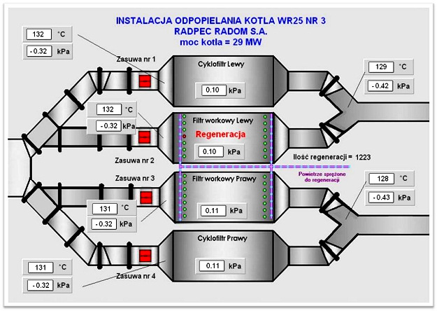
Asix system screen shot
Continuous emission measurement:

Screen shot of the momentary continuous emission measurement.
The currently allowable emission values are highlighted in red.
The WR 25 boiler after modernising the pressure part and the boiler setting

In case of reduction of dusts, general tightness of the boiler is very important. Prior to the modernisation of the dedusting system it is important to modernise the pressure part and the boiler setting.

Preliminary MFGD with the suction system.
WR 25 boiler - dedusting.

Discharge of dusts from the cyclone filter of the WR 25 boiler no. 3

Supply and regulation of all boiler fans is completed via frequency converters. The photo shows the cabinet with converters.
In 2014, Radomskie Przedsiębiorstwo Energetyki Cieplnej „RADPEC" Spółka Akcyjna organised two school educational trips to the "Północ" Heat Plant as a part of promotional activities dedicated to rising awareness about the meaning of Norwegian Financial Mechanism for the implementation of the "Limiting of flue gas emission by means of modernising the WR-25 boilers at RADPEC S.A." Project. Promotional activities are performed in accordance with the "Regulation on the implementation of the Norwegian Financial Mechanism 2009-2014 adopted by the Norwegian Ministry of Foreign Affairs pursuant to Article 8.8 of the Agreement between the Kingdom of Norway and the European Union on a Norwegian Financial Mechanism for the period 2009-2014 on 11 February 2011, as amended on 15 December 2011 and on 14 March 2013", especially with Annex 4 – "Information and Publicity Requirements".
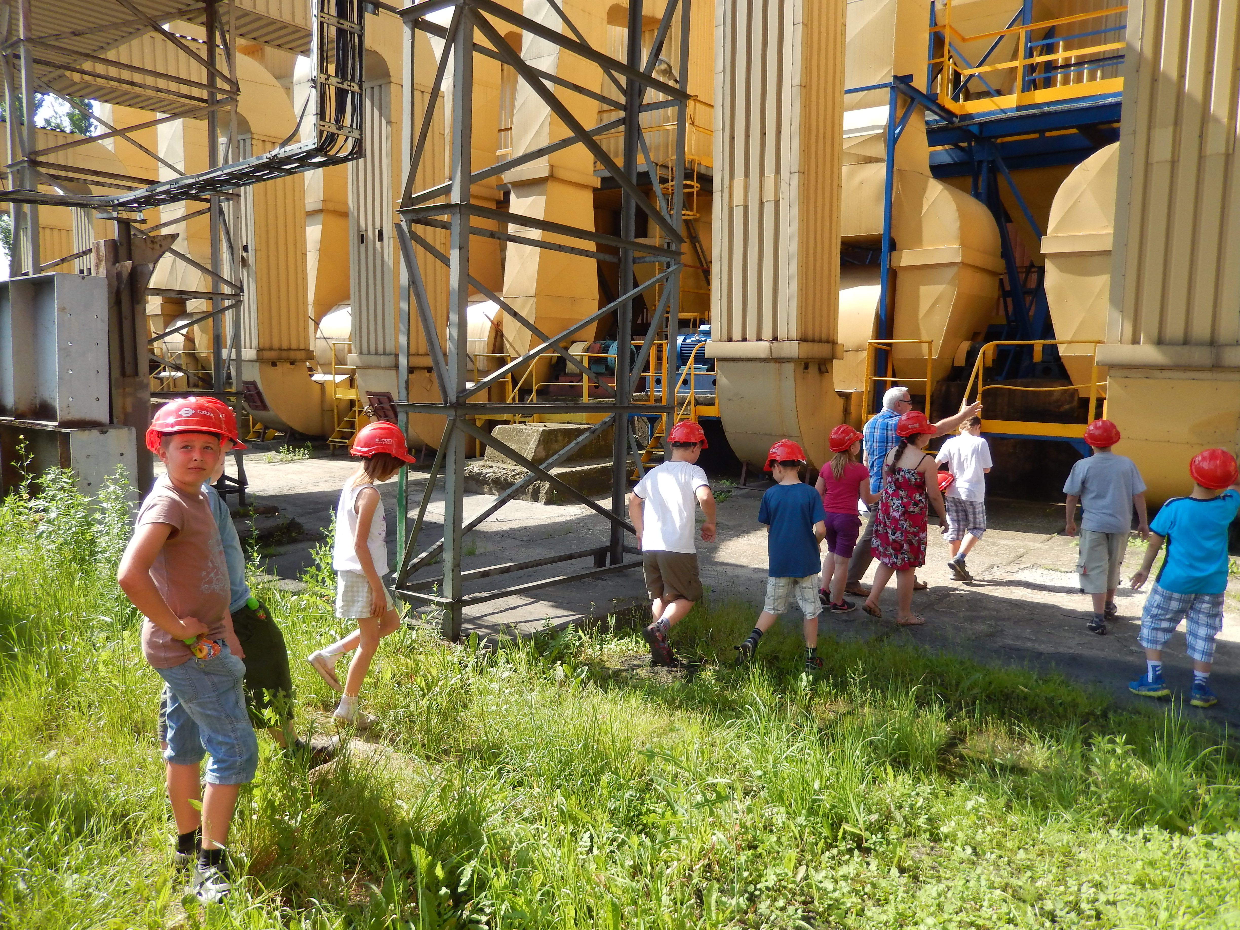
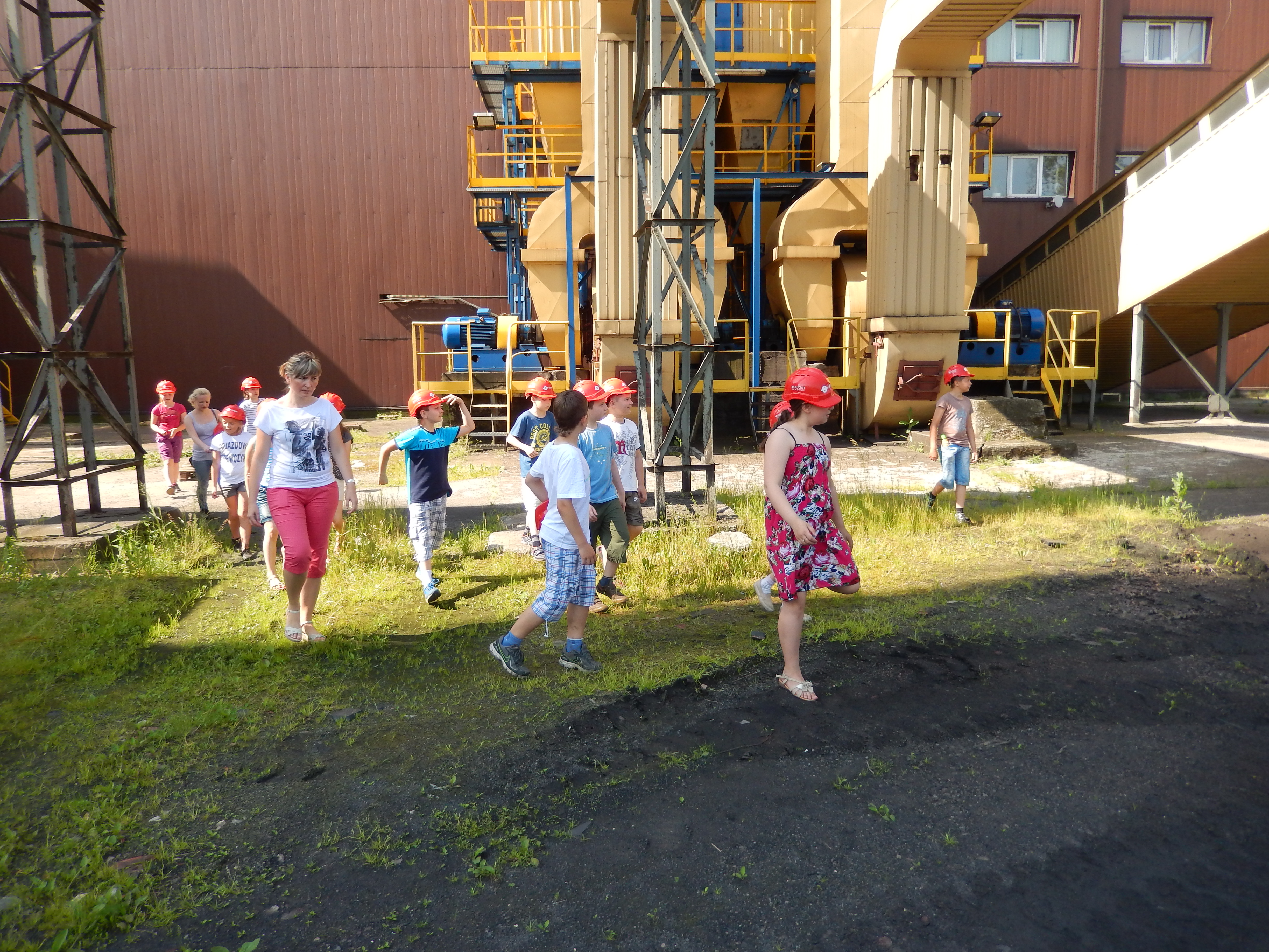
1. The first educational school trip to the "Północ" Heat Plant, where the Project is implemented, took place at 10 June 2014. The participants were students from the nearby tuition-free Primary School (PSP no. 19 in Radom) who first took part in the presentation "Where does the heat come from?".


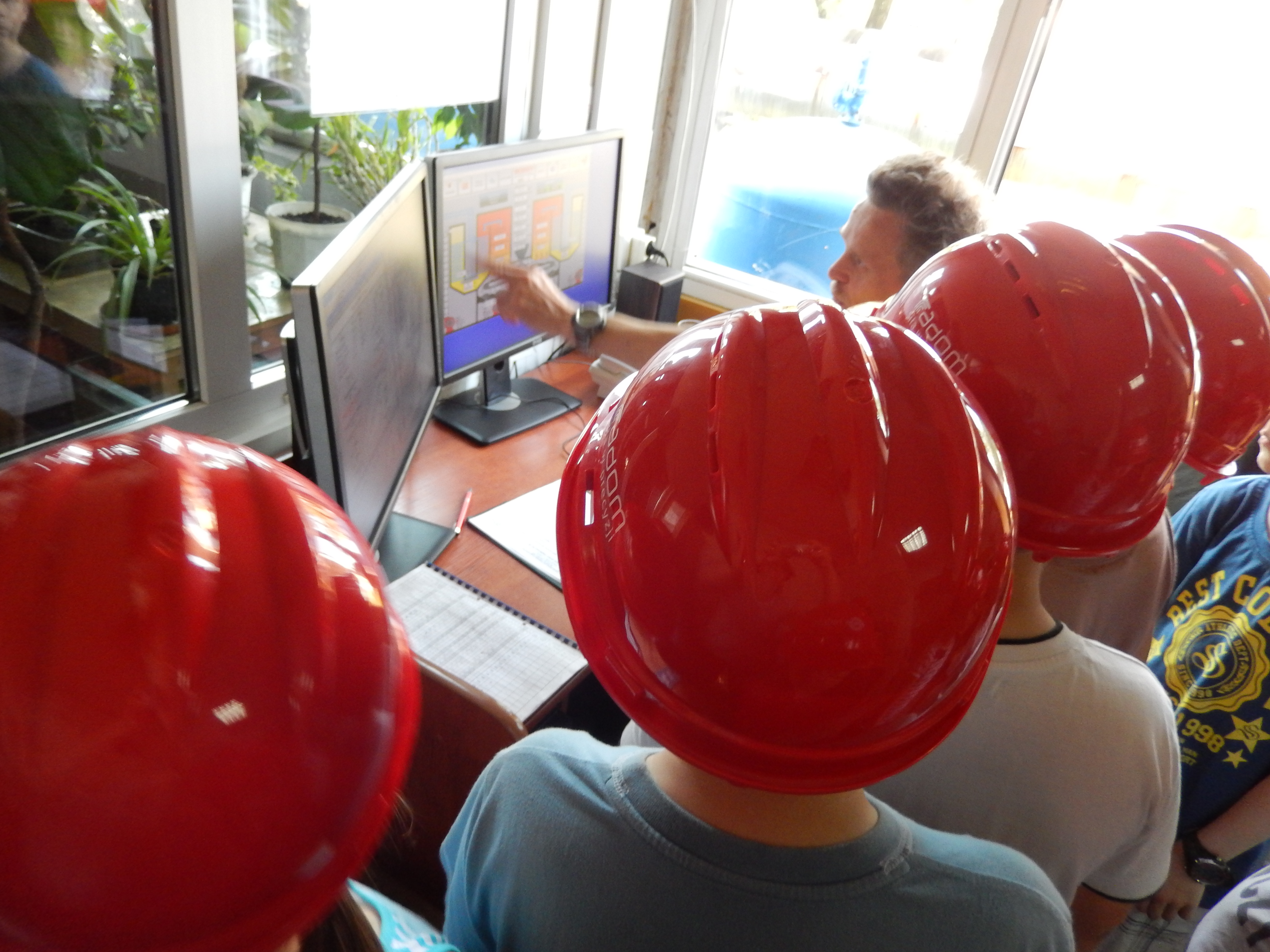
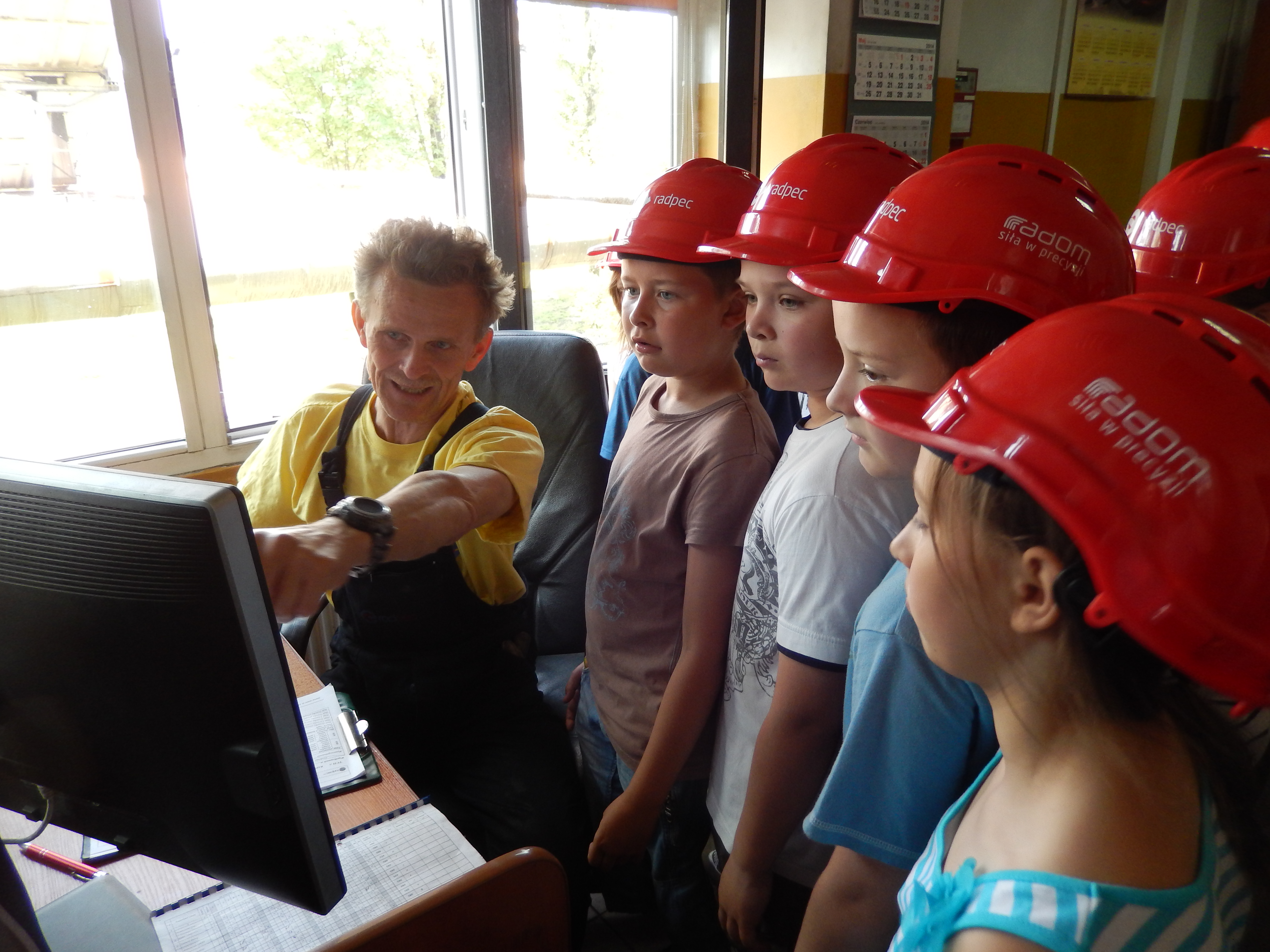
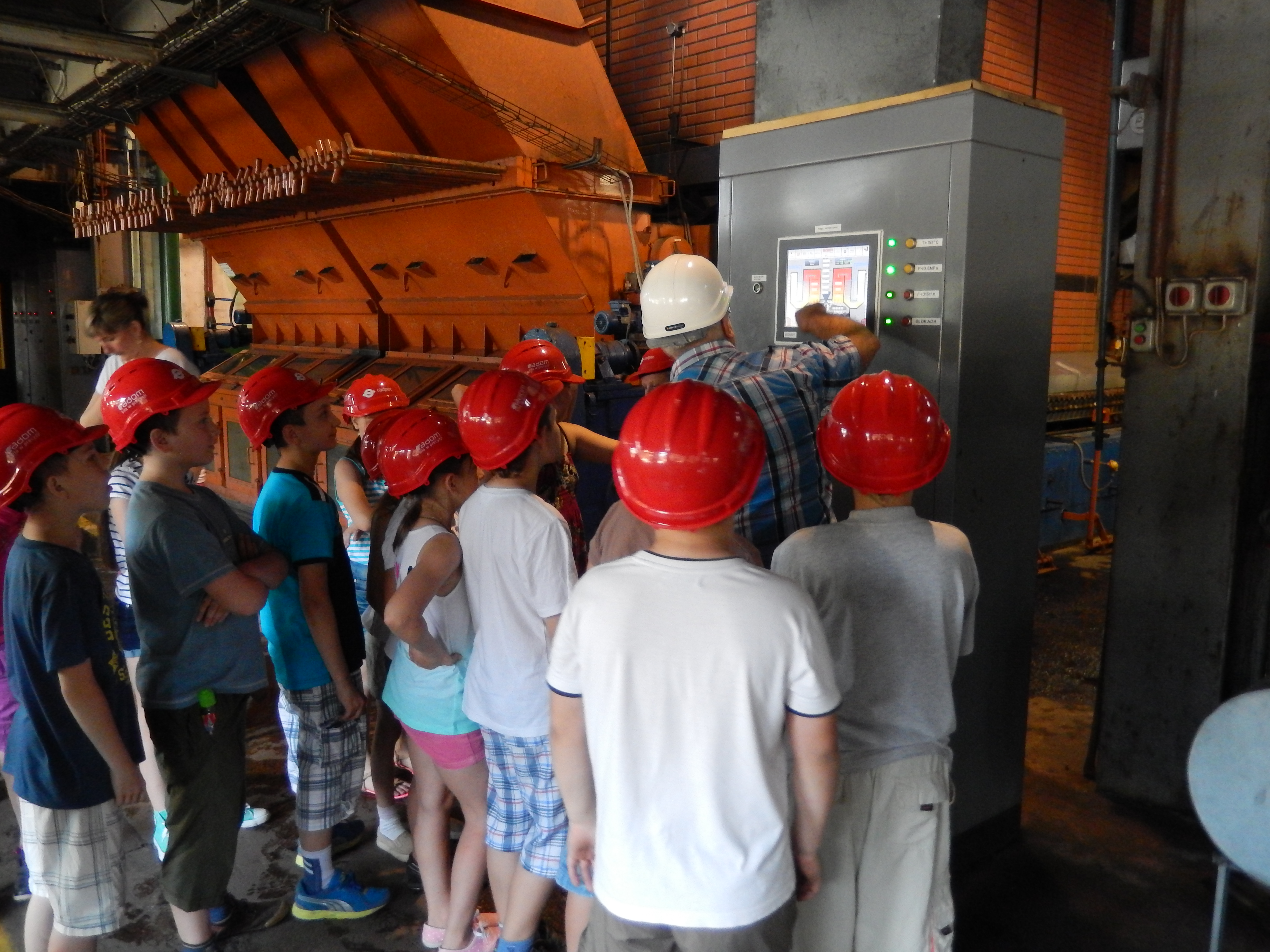
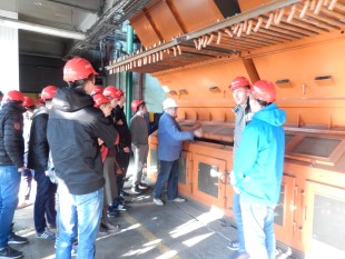
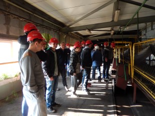
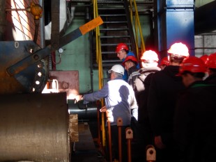
After the first activity, students took a tour around the “Północ” Heat Plant, discovering what the heat generation looks like and how the “Limiting of flue gas emission by means of modernising the WR-25 boilers at RADPEC S.A.” Project is implemented. During the tour, students learnt what ecological effects the Project will have after its completion. They also found out that the project is being implemented thanks to Norwegian Financial Mechanism grants.


After the tour, students took part in the competition testing their knowledge gained during the visit. The winners were awarded with special RADPEC gadgets (crayon boxes, pendants and reflective lights). All children were given the “Czerwony Kapturek w mieście” [Red Riding Hood in the city] storybook – an educational tale about smart use of heat power and environment protection.
2. The second educational school trip was organised on 29 October 2014 for the students of the Secondary Technical School of Electrical Engineering which is part of the Tadeusz Kościuszko Technical School Complex in Radom. Students, preparing to become power technicians, first took a tour around the plant and then watched a presentation about “Limiting of flue gas emission by means of modernising the WR-25 boilers at RADPEC S.A.” Project, co-financed by Norwegian Financial Mechanism. They were also given informational materials about the project (fliers and print-outs from the presentation).


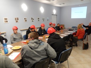

The last part of the visit was a tour around the “Północ” Heat Plant, where the students had an opportunity to view the development of the Project which they learned about from the presentation.

Implementation of the 2nd stage of the Norway grants project

The scope of the second stage included:
1. Modification of the third pass of the boiler (WR-25 no. 4) including installation of an additional water heater instead of the existing tubular water heater.
2. Execution of heating surface automatic cleaning installation based on the Entex technology.
3. Purchase and installation of pyrite flaps (2 pcs.)
4. Execution and installation of pyrite funnel manholes (2 pcs.).
5. Safety valve replacement (2 pcs.).
6. Execution of new thermal insulation of the boiler.
7. Supervision over boiler drying as performed by the investor representatives (servicing the "North" Heat Plant).
Blow air system modernization executed under the project included:
1. Modernization of the boiler-side air system together with the change of the place of blow air fan installation (moved to the deslagging level), execution of new air suction and feed ducts. The fan intake ports were installed at the stoker level (as in case of other boilers).
2. Execution and installation of two radiator air heaters.
3. Replacement of the existing WWOax-63 blow fans with the new ones applying the parameters appropriate for the WR-25 boiler, in a sound-proof casing with fan inlet and outlet silencers.
4. Development of technical and as-built documentation of the blow air system.
The scope of works related to the Instrumentation, Control and Automation (ICA) under the project comprised:
• replacement of water and flue gas temperature measurement systems at the WR 25 boiler no. 4,
• replacement of pressure measurement systems at the WR 25 no. 4 boiler,
• installation of water heater control valves automatically controlled from the control panel of the ICA control cabinet at the WR 25 no. 4 boiler,
• assembly and start-up of boiler power system, control system and measurement visualization.
The scope of electrical works comprised:
• modernization of the power system of the primary blow air system, moving the power and control routing of the blow fan motors to the deslagging level,
• replacement of the power, measurement and control routing within the WR 25 no. 4 boiler with wire mesh cable trays together with accessories.
Dedusting system modernization consisted in the following:
1. Disassembly of the existing system of flue gas cyclone separators as well as flue gas ducts in the scope enabling cyclo-filter installation.
2. Execution and assembly of a cyclo-filter system in place of cyclone batteries with a possibility of alternative operation (bag, mechanical and mixed operation in a parallel system).
3. Execution of the dedusting system retaining the existing mode of flue gas removal via fans with 75kW motors (2 pcs.).
4. Replacement of flue gas ducts from the boiler to the flue gas fans together with installation of slide gate valves enabling operation in 2 dedusting options as above.
5. Adaptation of ash chutes to the existing FULMAR 125 transport system collecting dust which accumulates below the installed cyclo-filter.
6. Execution of a comprehensive set of cyclone separator operating platforms made of WEMA grating with safety railing and ladders covered with yellow warning corrosion-resistant coating.
7. Execution of thermal insulation of the new flue gas dedusting system, made of mineral wool, coated steel and coated corrugated steel cladding.
8. Performance of high-temperature corrosion-resistant coating of the executed and installed elements.
9. Development of technical documentation within the scope of construction, assembly and start-up works.
10. Replacement of flue gas ducts executed for the purposes of cyclo-filter.
11. Execution of the compressed air installation providing cyclo-filter cleaning agent.
12. Replacement of WPWD - 80/1.8 flue gas fan rotors, flue gas fan housing, flue gas bearing housing and bearings, omega couplings, fan balancing.
13. Measurements confirming the dedusting efficiency as assumed above for each option.
Modernization of the dedusting system was assisted with a relevant scope of electrical and ICA works.

Photo 1: Installation of the draft passage fan housing
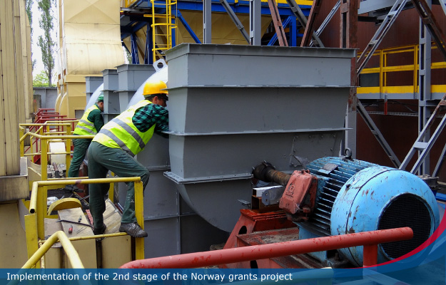
Photo 2: Installation of the draft passage fan compartment

Photo 3: as above

Photo 4: Painting of the dust collector supporting structure

Photo 5: Installation of the flue gas duct components of the draft passage fan

Photo 6: Installation of the flue gas duct thermal insulation and protective plates

Photo 7: Final visual effect
The "Norwegian" Project Completed
On 31 December 2015, RADPEC S.A. held a press conference connected with the completion of the “Reduction of Flue Gas Emission by Modernizing the WR-25 Boilers” project. The project was conducted from June 2012 until December 2015 within the framework of the Norwegian financial mechanism.
The attendees of the press conference were provided with key information about the completed project: a system due to which the boiler’s efficiency and flue gas dedusting effectiveness were increased. The presentation was followed by a reference visit at the investment project site.

The conference was attended by Zbigniew Słowiński – Deputy Chief Technology Officer, who discussed the project and presented its stages, Barbara Kaleta – acting as Financial Director, who presented financial aspects of the project, as well as top management of the Company.
The formal completion of "Norwegian" project.
On July 28, 2016 Radomskie Przedsiębiorstwo Energetyki Cieplnej RADPEC S.A. received information from National Fund of Environment Protection and Water Management, that the Final Report realization of project entitled: Limiting of flue gas emission by means of modernising the WR-25 boilers at "RADPEC" SA. was approved.
According to this, RADPEC S.A. on August 10, 2016 received final payment in amount of 540 000 PLN, and this is treated as formal project completion.

Radomskie Przedsiębiorstwo Energetyki Cieplnej "RADPEC" Spółka Akcyjna is a company with 49 years of tradition. Its field of activity is generation and distribution of heat.
The Municipality of Radom is a majority shareholder of the company.
"RADPEC" own the town's heating network. Its length is 167.8 km and it supplies heat to 941 district heating substations, 631 of which are modern, fully automated stations fitted with metering equipment and operated by the company.
The company generates system heat which is distributed to residential buildings, industrial plants, institutions and public utility facilities.
In 2004 Polish Center for Research and Certification granted RADPEC with the Integrated Management System Certificate: "Quality, Health, Safety & Environment". This certificate confirms that the company complies with the international ISO 9001, ISO 14001 Standards and Polish PN-ISO 45001 standard. In 2013, the renewal audit was carried out successfully, and the company was awarded with the ISO certificate for the next three years.
Main goal of RADPEC is to fully satisfy its clients and to win recognition as a reliable company which is taking into account best interest of all its partners, shareholders and employees.
Radomskie Przedsiębiorstwo Energetyki Cieplnej "RADPEC" Spółka Akcyjna
Address: ul. Żelazna 7, 26-616 Radom
Phone/fax: +48 48 36 255 00
Ten adres pocztowy jest chroniony przed spamowaniem. Aby go zobaczyć, konieczne jest włączenie w przeglądarce obsługi JavaScript.
www.radpec.com.pl
KRS no. 0000050068
NIP no.: 796-01-01-620
Share capital: 119,719,570.00 PLN (paid in full)
REGON no.: 670929493
Bank account (at PEKAO S.A.): 04 1240 5703 1111 0000 4897 3254